1968 4x4 vw bus
37" double beadlock
1 ton axles
5.7 Chevy v8

As of 4/7/18: I apologize for the delay of getting these pictures back up. But looks like I finally have all of the pictures back in this blog. Enjoy the adventure.
Hi, my first Blog ever. My name is Steve Rice. I am doing this to document the progress of my latest venture. I have been wanting to build a true 4x4 VW bus for quite sometime. Well, it looks like it its going to happen. Probably not nearly as fast as I would like it to. My goal is to publish as many pics as I can with tips that I learn along the way in the event someone else would like to do the same. (LEGAL NOTE HERE: This is for ENTERTAINMENT purposes ONLY. IF you decide to do any of this on your own, you accept full responsibility for your actions and decisions.....)
Now lets continue:

This is my 1968 Bay window that i just aquired some time ago (not bad for $150 ).
Below is my CJ7 that I will be putting the bus body onto:

I will try to keep this updated when I get through the different stages.
After spending some time with CAD program, and taking a lot of measurements, this is what I have come up with. I will be removing the Stock 304, and installing a LT1 rated at 300 HP with an automatic transmission. To accomindate the longer tranmission, I will be relocating the engine forward about 12". ( update: engine was moved about 5" forward and 3" lower). The radiator and battery (update: twin battery brackets were located under the body behind the rockers. Additional batteries can be added later in the rear as an option) will be located in the rear.

10/12/10
Spent some time on Sunday re-arranging the back yard. Monday it was time to get a little dirty. Jacked up the front and removed the front axle. If you are going to do this, remember to get rid of the shifting linkage and parking brake cables FIRST!!!
Here they are side by side

Front axle assembly removed

Under the front of the bus without the axle

The rest of the junk under the front that will be removed next


10/14/10
Yesturday I spent a couple of hours removing the rear end and the heat duct that goes down the spine of the bus. I thought about which would be the best way to remove the rear end (unbolt what I could and leave the rest, or cut out the whole frame assembly which holds the rear end). I decided to just cut out the frame to eliminate more weight. It was pretty easy, and faster since I dont need the frame for any type of support. I used a plasma cutter (I love that thing) and then used a Sawzall for the top section of the frame. The steel cut much easier with the sawzall than I expected. I guess it is due to the lower quality steels used back then. If I would have known it would cut that easy, I would have just used the sawzall (maybe next time).
Here is the rear end removed with a small section of the frame.
(picture lost)
Well, its been a couple of weeks since I have been able to do anything. Sunday I got a chance to get some work done. I started stripping the CJ7 down. Took me 4.5 hours to get it down to the frame (Thanks Marty for helping me get the tub off )

Got the Cj7 frame in front of the bus to slide it under

Went to jack the bus up just a liiittttlllee bit higher to get the frame under it, and the whole bus came crashing down. Luckily I wasnt under it.

So now it looks like I need to get some other jacks to do this a bit safer :)
spent a couple of hours Monday getting the bus aligned straight and pressure washed the frame/engine/trans of the CJ7. Next I will remove the motor-transfercase assembly and then try to get the frame under the bus again. Hopefully without the big crash this time.

WOW...what a past few days!!!! I was determined to get the body on top of the frame with out killing myself. Theory this time was a bit different than before. Instead of lifing the whole bus body up, we just lifted the front up high enough to slide the rear of the jeep frame in underneith. That way the front would be supported. Then jacked up the rear (SLOWLY). by the time the back was high enough it was dark. I started again the next morning to get the frame under the bus. took a couple of hours, but in the end, I am happy!!!!! (Once again....THANKS MARTY!!!!!)


11/9/10
Ok got some time to get some real work done this weekend. Got the bus all squared up on the frame and set it as low onto the jeep frame as possible. In the end, the bus frame is only 1.25" above the jeep frame. That seems to look pretty decent. I will have to do a little trimming on the rear wheel wells (which I had already planned on) and maybe a little trimming on the front wheel wells for travel. Then start to weld on the body mounts.
I used 2x4 .125 wall steel tubing on edge. This worked out well because I was able to leave out the body lift spacers that was on the jeep. The new mounts sit right on top of the rubber body mounts.

Here is a pic of both right side mounts:
A close up of the welds:

Once I had the 4 side body mounts secure, I was able to remove the front support bracket and rear jacks. Now she is starting to look like something.


Next I will need to start re-working the steering box. The current steering shaft from the bus is in front of the box, and the box is facing the wrong way. I think that I have a plan to make this work. I will post as soon as I have something.
11/26/10
last weekend I spent some time working on the bus. I have the steering box turned around (temporarily), and I think that it will work. I am holding off making the custom brackets since I might be getting another steering box that may fit better.
The brake master cylinder looks like it will fit great in the original bus location. Not enough room to but a power booster system on though...too bad. Future upgrades will include a rear disk conversion to stop better and hopefully a Hydro-boost system. But that will be a while.
I spent some time checking out what my suspension travel will be. The rear wheels are complete, and the tires fit under quite nicely.


I started to jack up a front tire to get an idea of the front wheel well clearance. As suspected, the tires hit pretty early. I want to keep the bus body as low as possible, so I will have to cut the wheel wells up front.
Front tire jacked up initial contact point before cutting

rough cut in front of the fender


Looks like I will have to go almost all of the way to the door line. My plan is to weld 1/8" plate alont the lower radius edge so that if there is some contact, it wont just fold in the sheetmetal.
The front jack point was right behind the front tire, so that had to go.

1/18/11
OK, finally, with the weather getting better, I was able to get some work done on the bus. Welded in the front frame extensions, mounted the brake master cylinder.
Here is the power steering box, reversed and flipped. I will add a skid plate to protect the fittings.
(picture lost)
Here is the front frame extension. Only tacked in right now since I am running out of gas in the welder :(b You can see the fish plate I put in for reinforcement.

And here is the Brake Master cylinder. I was able to mount it in the same location as the stock master cylinder. I had to cut an access panel in the floor board to gain accces to the top cover. I will fab a cover plate to hide it.

Dont have pics of the air tank yet, will try to get one shortly.
7/19/11
Well it has been awhile since anything has been done, but got some time to make a little bit of progress today.
Pulled the LT1 out of the boat and ready to set into the bus:

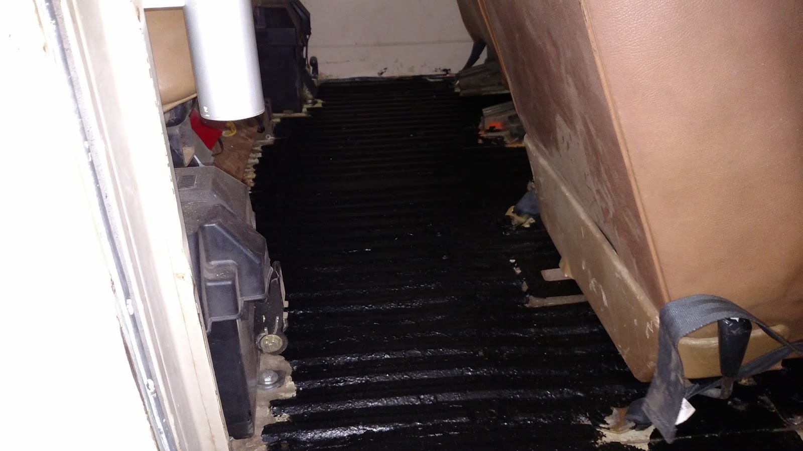
Spent this morning cutting the access hole in the floorboard of the bus. There was quite a bit of material to remove. Not only the floor board, but several hydraulic lines had to be removed (not going to be used anyways) and a section of the frame---a cross member.

Below is the TH350 tranny mated to a NP203 transfer case. Not the ideal transfer case to use, but it mates to the tranny. Someday I hope to run a NP205/203 combo, but that will have to be down the road aways.
 That transfercase is SEROIUSLY HEAVY. I need to get some plywood to act as a floor so that I can manuever the engine stand and lift. Working in a back yard is the not the easiest way to do things. Until next time:)
7/25/11
Spent some time yesturday getting the motor in the bus.
(THANKS TODD FOR YOUR HELP!!!!!)
We discovered that the best way to support the engine was to put the cherry picker through the passenger side door. We didn't put the motor in that way, but after looking at it, it looks like it would fit pretty easily. Otherwise, you have to put the engine in through the side door, set it down, move the picker and then lift the motor up again.


Front of the motor (not final position yet). Later we moved it back and down. Will have to get some more pics when it is in its final position.

Rear view of engine (pushed back) but will be lowered some more.
8/27/11
Ok, its been a while since I have done an update, so here we go. I have been busy, Finally got the engine set into its final position, motor mounts welded in, and transmission set into place. A few notes here. Fitting a 350 in here has been quite the challenge. If you like Ford motors, a 351 would probably fit better since it has a 60° engine versus Chevy's 90° engine. I have about 3.5" of clearance on each side. Not as much as I would like, but it is what it is. I have a set of small headers, but they wont fit. I will be getting ahold of some stock exaust manifolds which look like will fit nicely. Due to the tight clearances, I opted for rigged motor mount. I didn't want the engine hitting the sides of the bus frame. Remember that if you do this, you MUST still use rubber or urethane tranmission mounts. If the tranmission mount is solid along with the engine mounts, there is no room for frame flex, and something WILL break.
Here is the engine in its final location. The motor mounts ended up being about 8" forward and 3" lower compared to the original location. This was done for a couple of reasons. First, I wanted the rear drive-shaft to be as long as possible. Secondly, I didn't want the bell housing to be in the passenger area. Care must be taken when moving the engine this far forward. It comes pretty close to the axle differential. In this case, that is ok, since I will have to limit the upwards travel of the axle anyways to keep the wheels from hitting the bus wheel wells. I will be counting on axle droop for my overall axle travel. If necessary, I might do a suspension lift or spring over conversion to gain more clearance, but I will run it first and see what my limiting factors are first.
(lost picture)
Pic of my motor mount before welding it to the frame

If you do use a Chevy motor (I am partial to Chevy anyways), look at an older motor that does not use a serpentine belt. Another issue that I had was getting clearance with the alternator, it sticks out pretty wide. Using a v-belt set up, will allow you to tighten things up a bit to gain some room.
Here is a rear view of the transmission. It is a TH350. There is room to put a 4 speed in later if I choose to. Even with the NP203 transfer case (not my t/c of choice, but hey, I already have it) my driveline will be a healthy 22" long. Thats pretty damn good. Down the road when I can convert to a np203/np205 dual case, my drive line will be even longer :)
Since I moved the engine/tranny so far forward, the skid plate didnt line up with the frame (let me back up for a moment here). The tranmission/transfer case came with just a cross-member. I didnt like that, so I modified my original skid plate from the 304 and manual trans to fit the TH350. Anyways, the Jeep frame starts to narrow just forward of the original location of the skid plate, therefore, the plate is wider that the frame. I looked into just narrowing the plate, but with all of the compound angles invloved, it looked easier to fabricate and weld on attachment points to the outside of the frame to bolt the skidplate to. I will gusset these later to make them stronger and use larger bolts.

Todd got a hold of some really cool aluminum steering u-joint with slip shafts. They are from '02-'05 chevy trucks (might be more years that have them). They will work GREAT. I will need to get a steering column bearing and attach it to the floor to support the bottom of the steering column (originally the bottom of the steering column attached directly to the steering gear box).

WOW, after all this time, I finally got some time to get some work done. I mocked up the location for the middle bucket seats and the rear bench seat. Remove the buckets, then fabricated the mounting brackets for the rear bench. Since the seat is from a Blazer, not only does the back of the seat fold down, but the whole seat pivots forward on the front mounting feet to allow for better storage options


Got the middle bucket seats mounted (try to ignore the seat covers, they will get replaced) The right seattilts forward to allow easy access to the rear bench

Got some more work done. Converted the side sliding door to hinge at the top.
then installed some hydraulic lifts that Kurt from KAL Offroad supplied me (thanks Kurt). The lifts have about 120lbs of force each. Plenty to hold up the door, but it looks like I will have to make some custom brackets for the end ball pivots. These are maxed out strength-wise and will fail from fatigue over time.


FINALLY got the steering system done :) The photo below doesn't show it, but there is now a brace tube that runs from the mounting plate to the passenger side frame. That plate does NOT move at all!!!!! The steering was definitely the most challenging hurdle so far. I don't plan on going into great detail as to how i did it other than the photos for 2 reasons. If someone else is brave enough to tackle this project, they should be able to figure it out, and I don't want the liability of the steering system failing because someone did it the way I did it. Don't get me wrong, I am very confident in my methods and will be very comfortable driving it. Another reason is that there are many other ways to do it depending on what steering box is used, what axles are used, what frame is used....etc.


6/5/13 Well now that I have the steering pretty much done: left goes left and right goes right (now aint that a good thing?) I have now moved to the rear of the bus. I have a radiator from a Chevy Blazer. It will supply plenty of cooling (and just for the record, good luck on getting a larger one squeezed in there). Below is a pic of the radiator on the lower mount

And then we have an over-all picture of the radiator set far back into the old engine compartment.
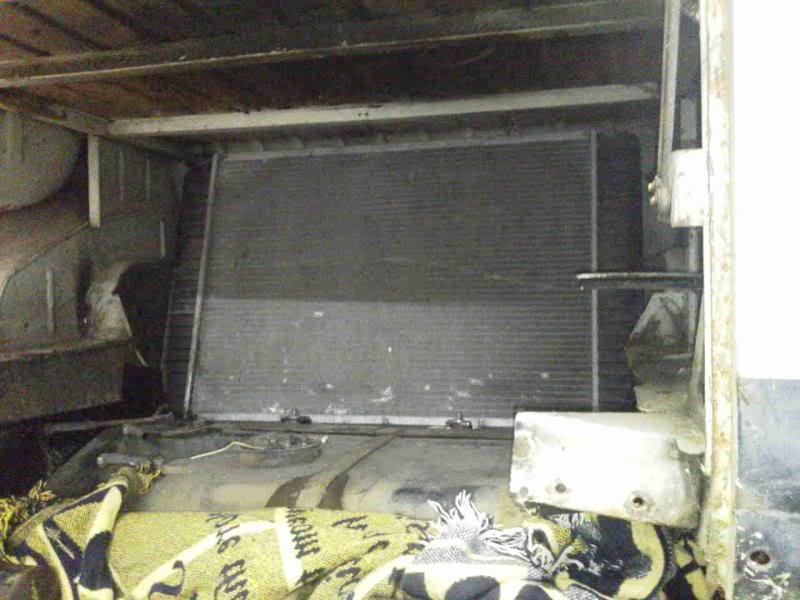
The plan will be to get a massive dual fan that will move over 3000 CFM of air (update, the one that I got, moved around 6000 CFM). I will also be building a shield over the gas tank to keep the tank from getting too warm.
6/9/13 Got some more work done this weekend. Finished the top radiator mount so that it is secured to the frame. I decided to secure the lower AND upper mounts to the CJ frame. I was concerned the the body would flex against the frame too much. This way it can flex all it wants, and the radiator will stay in place. I also sand blasted my mirrors. The previous owner thought that a random camo paint scheme would look nice (Blazer)...YUCK. then painted them silver and mounted the passenger side for now. Will get the drives one mounted later.
Before:

After:

I know that I haven't been posting much lately, sorry about that!!! I've been working on the body mounts. There are a total of 10 of them using 5/8" bolts. I figured that should hold things in place.


(Later update: Everyone's consensus was a no-go. After further thought, I liked the idea of having the windows available for emergency egress, so they never did get mounted)
I also started working on the exhaust manifolds. I was originally going to run headers, but there was absolutely NO WAY they were gonna fit!!!! Trying to remove the old air injection tubing from the manifolds proved to be useless, even after they have been sitting with penetrating oil for over a week. Ended up just cutting off the tubes and welding the holes shut, then cleaned up the welds. Not too bad, and there is absolutely no way anyone will be able to see them anyways once installed.

Next step is to remove the spark plugs, spray some oil into the cylinders and turn it over (it's been quite some time). Then install the manifolds. It is so tight that the only way to get them to fit is to come up from the bottom.....yipee.
Worked on the remote latch for the side door. Sorry the video is too close up, it was a bit difficult to hold the camera and operate the latch at the same time
How to install exhaust manifolds on a VW bus with a LT1:
Cram engine hoist through side door

Once manifolds are secure lower engine. Create new language (not necessarily appropriate for children or mothers)

Enjoy a beer 
Ok, got some more work done. Finished the side door latch and trimmed the cables, so on to the next project. I got a hold of a 22 Gal race fuel cell from Kal-Offroad. The CJ7 tank was only around 18 gallons. The biggest issue with the original tank is how SMALL the fuel fill line is.

You can see it on the right. Filling up that tank has always been a pain in the butt.
Here is the fuel cell.
.jpg)
As you can see, it has a massive fuel fill, which coincidentally matches the large fuel fill of the bus :P
Had to fabricate a new skid plate to support the tank out of some steel plate. The bottom of the tank is lower than the original, but since the bus body is longer the the CJ7 body, my approach angles change. Looks like I wont have any problems with hitting anything and it does lower my CG a bit.

3/24/14
Relocated the bumper into the right location, painted and bolted into place

Then I started to fab up the side rockers
here it is mocked into place


cut and tacked in the support brackets

Here it is the rocker tacked in place

The plan is to get it over to Kal Offroad this next week. There we are going to plumb in the radiator, power steering, brake, and tranny cooler lines.
4/5/14
Pulled the bus out for a little sunshine. Kurt from KAL Offroad is coming over with a flat bed trailer. We are taking it over there to install the cooling and hydraulic lines (and who knows what else we will do while it is there). While I was waiting, I took some time to see what kind of travel I can get out of it.

Bottom of the tire is 21" off of the ground before the left rear tire started to come up. Still was pretty stable.
This picture is just for fun. Couldn't help from taking a pic of the bus next to my Spitfire.

4/18/14
More stuff done. Grant and Kurt helped me get it over to KAL Offroad where we pulled the wheels off to start with the brakes


Got the brakes put back together on the front. New rotors, calipers, pads, studs, locking hubs, 18" stainless DOT brake lines, and all new steel brake lines through-out the bus. THANKS KURT!!!!!
10/15/14
Ok, So I know that it has been awhile since I did an update. I did take a bit of a break, but now I am back on the project. Installed the dual radiator fan onto the radiator...HOLY COW, does that thing move some air. Should have NO problems keeping the engine cool. 6000CFM!!!

I also added some serious insulation over the fuel cell, and then covered that with a sheet of stainless steel. Should not have any issues with the fuel tank getting hot. Also note the 2.5" fuel fill line, This thing will fill up fast. Not sure if I will run into issues with the line being right behind the fan, but I will test it out and then see if any changes need to be made.
I also built the bed frame that goes inside and it h old the mattress quite nicely and provide some nice storage accessible from the rear hatch. (pics to come).
Ok, here are the pictures from the rear of the bus of the bed. Rear shot with the door closed:

Top rear hatch open showing the mattress folded which allows the rear bench seat to be in the up position:

And here is the bed folded out for sleeping, hangs over the folded bench seat. Pretty comfortable.

11/15/14
Ok, Got some more stuff done this weekend.
Pulled all the wheels off again and got her up on jack stands.

Hooked up the cooling tubes that run the length of the bus to connect the engine to the radiator. Here is a shot connected to the LT1. Tight fit, but does clear.

Coming down from the engine (driver's side). Welded tabs along the frame to hold the cooling tubes.

The cooling tubes connected to the radiator. In the back ground you can see the passenger's side going straight up tot he top of the radiator.

Another view of the driver's side while mocking up the Fox shock. I have over 12" of suspension travel, so these 14" shock will give me a bit of fudge room so I don't max out the shocks.


12/6/4
Been doing some more work on the bus project. Received the wiring harness. Looks simple, don't it?

Sorting out the mess. Some wires had to be moved since there are things not in the "normal" position, like the radiator.


Cleaning all of the terminals on the reverse light, tail lights and dash switches.


Reverse lights are working!!!!!!!

Tail lights are working!!!!!

Got the windshield wipers to work. They were pretty stuck at first (who knows how long it has been since they were run 15+ years???? The "park" mode even works :)
4/3/15
Got some more work done. Welded a tab so that I could mount all of my relays together on one convenient and safe place: Radiator fan #1, Radiator fan #2, Fuel pump

I wanted to use the original parking brake arm & handle. The pivot was completely frozen solid. I cut out the bracket,

Beat and soaked the pin for 2 days. Finally got it out, cleaned, lubed and put back together.

Instead of welding the bracket back into place, I fabbed up a plated out of 1/4" steel plate so that I could simply bolt the unit back onto the bus. Glad that I did this, since now it allows me to remove the whole assembly quite easily while making other changes.

Once all connected, I realized that I was not getting enough travel out of the stock handle/arm to fully actuate the rear brakes of the CJ7 drive train. I cut and extended the lower arm.

Welded on the control cable housing support and attached the cable to the extended handle. Works great. I was surprised how much the cable stretched. I had to re-adjust the cable several times, but now they seem to be holding great

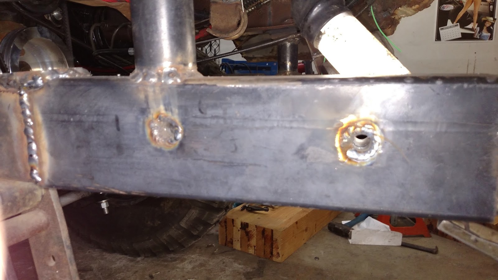
I also permanently mounted the front seats. The front mounts are hinged so that I can tilt the whole assembly to gain access to the engine. Soon I will fab up the engine bay to cover up the engine.


These are the plates that I made. Nuts are welded to the plates and the plates are welded to the underside of the front wheel wells. This makes removal of the entire front seat assembly a 1 person job.

That's it for now. I don't even want to count the hours in this project so far. Keep an eye on here. I hope to be making some major progress over the next few months. Plan is to actually DRIVE it by July/September.....ya right
5/19/15
Been getting a bit more done on the bus. When I originally set the skidplate/cross member, I was using a NP203. Since then I have acquired a NP205 which a MUCH better transfer case. Unfortunately, with original unit would not work. But, that's OK. I was never really happy with that set up anyways. I cut off all of the old brackets. Had a friend machine some bushings with a 1/2-13 thread tapped in them:
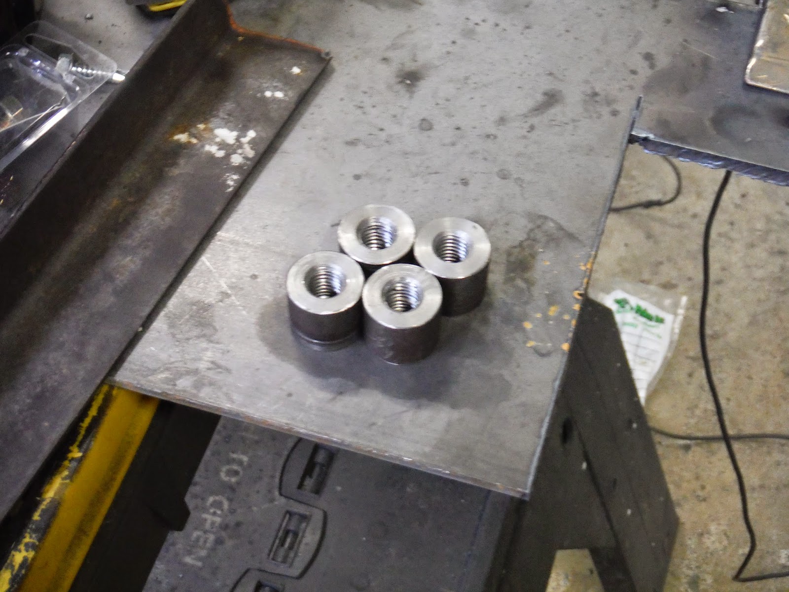
Cut some 1/4" plate and welded all around

Ground smooth on top

And then welded them to the frame. I did add a gusset to the forward edge. There is also a secondary jam nut on the forward bolt "just-in-case".

Over-all, I am quite happy with the way this turned out. It is much cleaner and simpler than what I had on there before. I will be getting some aluminum plate to make a skid plate for the transmission and engine.

Now that the transmission, torque converter and transfer-case are in place. I am working on the shifter cable for the transfer-case. Below is the bracket that attaches to the transmission to hold the rear of the morse cable. Who would ever think that something that looks so simple would take SOOOOO long to figure out and make.

Ok, So I went to put the front drive shaft in just to see if it would fit. Length wise, it will (at least temporarily, will need to get a longer one). Unfortunately, it hits the tranny oil pan. This is not too surprising since I lowered the engine so much to keep the CG as low as possible. So I had to modify the tranny pan. Looks OK :)

Back in October, spent some time re-arranging the shop to get some more space.

1/17/16Well, it has been quite sometime since I have had a chance to update this blog. Doesn't mean that I have not been working. Some major changes. I originally installed a LT1 engine. Why: well quite frankly I had one laying around and I thought fuel injection would be cool. Between the costs of getting the additional sensors needed and realizing that the Opti-Spark was not really the best suited set up for 4x4ing, I decided to swap it out for a standard carbureted 350 engine. Swapping the engine was actually quite simple - one weekend and done. I have also spent quite some time re-arranging the shop to get more usable space.

Ran in to a few issues. Crank pulley hit the frame, Power steering pulley hit the brake master cylinder. Modified the power steering pump bracket to move the pump out about 3.5". Bought all new pulley (crank, water pump, alternator, and power steering-- a little chrome bling-bling never hurts) as well and a low profile air cleaner. It will clear the seat frame by 1/2".
Just for fun. This picture hit FB a few days ago and of course everyone is tagging me on it. Unfortunately, the are not real, but rather R/C trucks. Would be cool to have one though to go along with the real thing.

New Alternator and water pump pulleys installed

New billet aluminum crank pulley...can you say TIIIGHT fit?!?!?!?! This pic doesn't show it, but I did take a grinders and remove a bit from the frame so that I can get the fan belts on.

Faith was given the task of marking the tranny and engine oil dip sticks, cutting the both tubes and dipsticks, and re-marking the dipsticks with the cutting wheel. Worked out quite nicely. Both the engine oil and tranny sticks are within a few inches of each other....Nice job sweetie.

Building the dog-house frame. Radiuses were bent by Kurt at KAL Offroad. There will be sheet metal that runs from the forward cross tube down to the floor and the sides. The center section will be covered by the sheet metal that will be affixed to the bottom of the hinged seat frame. Foam tape all the way around. Should work out quite well.

Bought a new fuel pump, Kurt had fun installing that...thanks Kurt.

Removed the seats from the frame. welded on 1" square tubing to rest on top of the dog-house structure. welded a center plate to hold the ratchet shifter. Had to order a custom cable for it. I new that the 5' cable that came with it would be too short. Could have gotten away with a 10' cable, but got the 12 footer for some extra wiggle rooms.

12' foot cable should be in on 1/27/16. I also order the Evans waterless coolant program. I like the features and benefits, especially the REALLY high boiling point so that it will not build up any pressure, will not rust or corrode any components, and have very good lubricating properties. Not very cheap stuff, but pretty cool.1/31/16
Filled the cooling system with the Evans waterless coolant.

Of course, after the system was filled up, the water pump started leaking out of the weep hole. Off to get and install a new water pump.

And I told my wonderful girlfriend ( who does NOT complain when I spend countless hours at the shop), that I would put her name on the door.

So I was pretty excited yesterday afternoon. Shifter is hooked up, throttle cable is hooked up (that was fun!!), all fluid are in, front drive shaft is bolted on (still need to have a rear shaft made). You know what's coming next right?????? You got it, lets see if it will finally move under its own power.
Engine start.............√
Parking brake off......√
Shifter in drive.........√
Forgot to lock the front hubs
Try this again, still no good. Not sure what is going on yet, will get back on it tonight. Front drive shaft is spinning, but not moving. I jacked up each of the tires, and it appears that the half-shafts are locked with the hubs. Last time I drove the vehicle (before disassembling) there were no issues with the front end. A bit perplexed right now. I REALLLYYY want her to move under her own power!!!!!
IT'S OFFICIAL:
On 2/1/16 For the first time....drum roll please.......she drives on her own!!!!!!!
Here we are at the end of the driveway. Went to turn around, put her in reverse, and No-Go. Had to put another quart of fluid in the tranny. I think that having the radiator all the way in the back, sucks some fluid. But after that, no issues.

Next on the list, exhaust system and rear driveline. I am going to see if it's possible to get all of that done this week. Maybe have it useable for Super Bowl??????????
2/2/16: Kurt and I pulled it out of the shop to give her a quick bath and check the fluids. We then put it on a trailer so that Kurt could take it to get an exhaust system put on.


2/22/16
Working on purging the cooling system. Being a bit of a challenge since the radiator is so far from the engine. I have 6 gallons of coolant so far, and just bought another 3 gallons. I don't think that it will overheat.
Installed some wheel spacers to bring the rear wheels out flush with the fenders.
before:
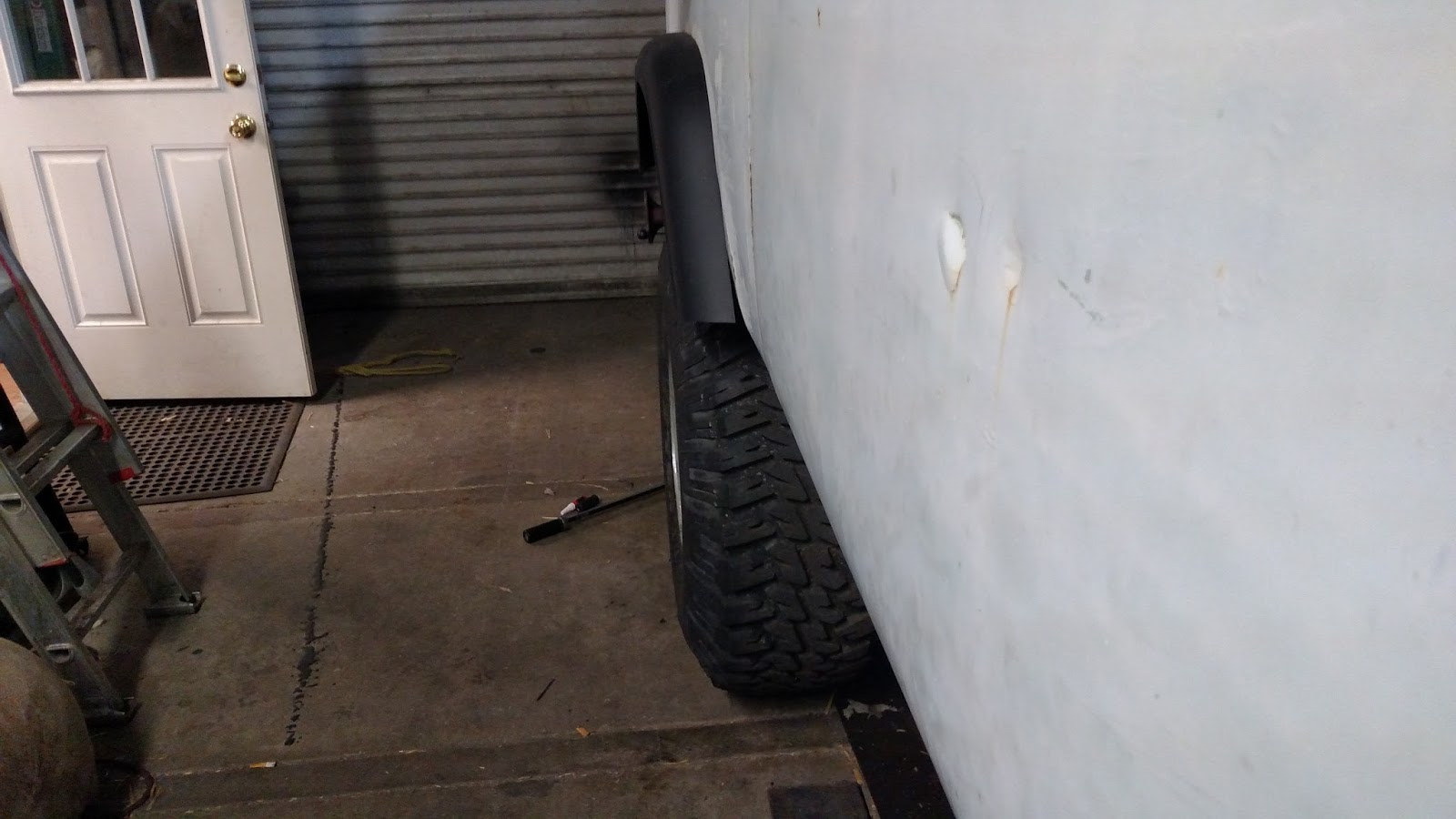
After

And started building a ladder so that people can get in the back.

3/6/16
Started work on the dog house this weekend. Welded up a steel structure. Then covered the frame with some stainless steel. Would have been much easier if I had a brake, but all in all, it turned out ok.


 My baby Faith was so sweet. She got me a stainless chromed emblem for the front. So we just HAD to install that.
We were already to load up and give a trial run. Weather is pretty nice, but since it rained hard last night, the river bed has too much water in it. Maybe next weekend.
https://www.youtube.com/watch?v=7jRZZUoRbOQ
Just some mild testing, nothing too wild.
Work on installing the bumper this week.
Here is the bushings welded into the frame.


Bumper brackets are welded to the bumper and slides onto the frame quite nicely.
Rear shocks have been delivered, parts for the front shocks will be here early next week as well as the LED light bars. Updates to follow!!!!
Time to load up the bus and take her to some place new today for more testing.
8/18/16
Some more updates to share. Installed a 10,000# winch. My goal was to hide the winch inside the body for a couple of reasons.
1 -- Protect it from the elements
2 -- Keep the CG further back and control the approach angle
3 -- It just plain looks better

If you remember, the window on the side door was broken (was that way when I got the bus). Bought a slider for the driver's side. So we removed the solid driver's side window and installed it on the passenger's side, then installed the slider on the driver's side.


3/26/16
Well We took the bus out last weekend to a friend property to test it out. For the most part everything worked out pretty well. Need to trim some more metal away from the wheel wells. The video is too large to put here, but you can go here:
Just some mild testing, nothing too wild.
Work on installing the bumper this week.
Here is the bushings welded into the frame.

Rear shocks have been delivered, parts for the front shocks will be here early next week as well as the LED light bars. Updates to follow!!!!
Time to load up the bus and take her to some place new today for more testing.
8/18/16
Some more updates to share. Installed a 10,000# winch. My goal was to hide the winch inside the body for a couple of reasons.
1 -- Protect it from the elements
2 -- Keep the CG further back and control the approach angle
3 -- It just plain looks better

Also note the new air horn and LED bar!!!! :)


We are getting ready to take her out to the dunes for the first time this weekend, so I wanted to increase her ability to be independent. Added an on-board air compressor with 2 gallon tank.

I am also in the process of putting together an on-board welding system (stick type). But not quite finished with that. Would be nice to actually get a stereo in at some point as well. Until next time....
Just some fun pictures of the bus out in her element.


Getting ready for a little BBQ

Few things that didn't get posted a while back:
Wanted a rack on top to hold the kayaks. Had some 6061-T6 aluminum.


Added a hand rail for the side door

Painted the floor with black bed liner

Wanted to add to my rocker panels. These provide a great stepping point to get into the rear of the bus.


I have been running without a spare tire for some time now. I know, not the smartest thing in the world (I don't have one). Anyways, I am working on putting 1 tons on this thing. S I thought that this would be a good time to build something to carry a spare when I get one.


Have been working on a bit of this and a bit of that over the past several weeks.
Since I have been driving the bus, I was never able to shift the transfer case from the drivers seat. I had to get out, walk around, open a trap door, and shift it manually. As you can imagine, not very practical. So now I have made a custom shift linkage that goes around everything. Doing that, I had to move the location of my engine gauges. So now I have a new center console (steel construction with stainless steel skins). All easily removable for maintenance


Finished my spare tire carrier (still need spare tire, will get that when I convert to the 1 ton axles) and finally mount my jerry gas can holders.

Added a stereo and amp awhile ago, but never did put of pics.


Time to start fixing up the Dana 60 for the bus.Already replace both slave cylinders, brake shoes, and cleaned up the drums.
Now shaving off the spring perches and shock towers

1/4/20
Took the bolt on skid plate off of the AMC 20, with some modifications, welded it to the Dana 60

Cut, grinded, and welded side gussets

Make larger gussets for the center section.


1/11/20
With the rear Dana 60 ready to be fitted, It became time to work on the Corporate 10 front. Now there are many that will ask why not use a Dana 44 or Dana 60. Regarding the 60: If I could have found one for a reasonable price, I would have. Around here, people seem to think they are made out of gold. Nice thing is, once the suspension has been modified ( the hard part), a new front axle can always be swapped out. Ad far as the Dana 44: This 10 Bolt was given to me for free. It is in reality, the same as a 44. And with my steering set up, I don't think that I will need the flat knuckle for high steer....we will find out if I am wring on this point.

I did a complete tear down to check and pack the bearings and installed brad new break calipers. Didn't take any pictures of that stuff since it's just normal mechanic type stuff. Next was to incorporate the front truck that used to be on my old Dana 30. Diver's side is welded to the axle (truss was originally just a bolt-on). I had to get creative with the passenger side so that I could get the U-bolts through. So the passenger side does bolt on with 3 1/2" bolts to the skid plate,

One of the largest challenges with installing full wide axles are spring locations. With full size axles, the springs must go over the axles ( in the front anyways. This would essentially lift the bus up an additional 6". That is the last thing I wanted to do. While I have to outboard the springs to accommodate the wider spring perches, I will also have to raise them up higher along side of the frame. This will essential leave the axle in the same relative position to the bus body. This of course led to the difficult challenge of getting shackles to fit correctly. My brother reminded me of an old trick that I had completely forgotten about. These are slider boxes. They replace the pivoting shackles (which act like "fangs" when hanging down in the front of a 4x4 rig). The principle is that the moving side of the spring will slide withing the box. This can also lead to some great suspension travel if done correctly.
Here is the box structure with the slots.


As you can see, even though the bus is significantly wider that the original CJ-7 body, the wheels still stick out much to far for my liking. I did pick up a set of 4 HMMWV Hummer H1 bead lock wheels. The large 7" backspace will counter act this plus give me double bead lock wheels. :)

2/8/20. You can see that the H1 Hummer wheels fit much better. I went through great lengths to keep the width as narrow as possible so that it will look proportionally correct, and fit on m,y trailer. When all was said and done, my outside tire to tire dimension ended up being 78.5"


3/7/20
While waiting for parts to come in, I decided to switch gears a bit. The original bus wheel is 17.5" in diameter. But since the bus now has power steering, I really wanted a smaller, more conventional size. Used a puller to remove the stock wheel. I'm sure that wheel has been on there since 1968.

Below is the stock steering wheel that pulled off my 1972 Spitfire. Come to find out, it will work perfect for the bus, well....except the face that the bus uses a spline shaft, and the Spitfire wheel bolts on.

Could buy and adapter, but where is the joy in that. Besides, there is no adapter for this combination. So let the fun begin. I cut the center section out of the original bus wheel. This will give me the spline that I need to fit over the steering shaft.There were 3 holes in the aluminum center section that I re-drilled to 1/4" and transferred those holes to 1 large washer (it's bigger than it looks in the picture). This washer fits perfectly inside the aluminum hub.

Welded the washer to some steel tubing, which was then welded to a steel plated with the hole pattern of the Spitfire steering wheel drilled, then painted.

Installed. Project took about 1.5 hours and only cost a couple of bucks.

3/14/20
So in the process of installing the upgraded front axle, I realized that it would be in my best interest in install hydro ram assist. With the weight of the bus along with running heavy 37" H1 military bead lock rims, I felt it prudent of taking the stress off of the steering box. Here is the bracket that was made to weld to the axle. It will hold the fixed side of the ram.

The ram comes with massive ball ends for 3/4" bolts. That size is just truly not necessary. I bought some 5/8"-3/4" bronze bushings. Grade 8 5/8" bolts will be more than strong enough.

Trial bit ram into the bracket.

Main bracket tacked into place, fitting the tabs I made for the other side of the ram onto the tie-rod. You will note that there is an additional tube welded onto the tie-rod. This is to spread the load as much as possible from the load of the ram. Wheel is set 3/16" short of full right stop, with the ram fully extended. This will allow the ram to be the steering stop, NOT the knuckle. Tacked these tabs in place.

A little note here. If installing on a full width axle, you would be looking for a ram with 8" of throw (some smaller axles use 6"). Move wheels from lock to lock and round down ever so slightly. The idea is that the limit of the ram is your stops: NOT the little bolt stops on the knuckles.Is that what I did....of course not, but I knew this ahead of time. I bought a 10" throw ram (1.5" bore). I bought this one because it had the rod ends that I wanted and was only $68.This longer ram made it more difficult to fit within the real-estate that I had.I will be installing external stops on the ram shaft so that the ram will be its own stop, and no use the knuckle stops .

Prime


And painted. Why not have some fun with colors. The drag link is painted the same color. Just wait until you see the axles :)


Spent a couple of hours wire wheeling and cleaning. Weather is not cooperating so much. Was able to get a good coat of primer on.

Since I wanted the axle to have some fresh paint, why not have a little fun. Should definately be visible under the bus

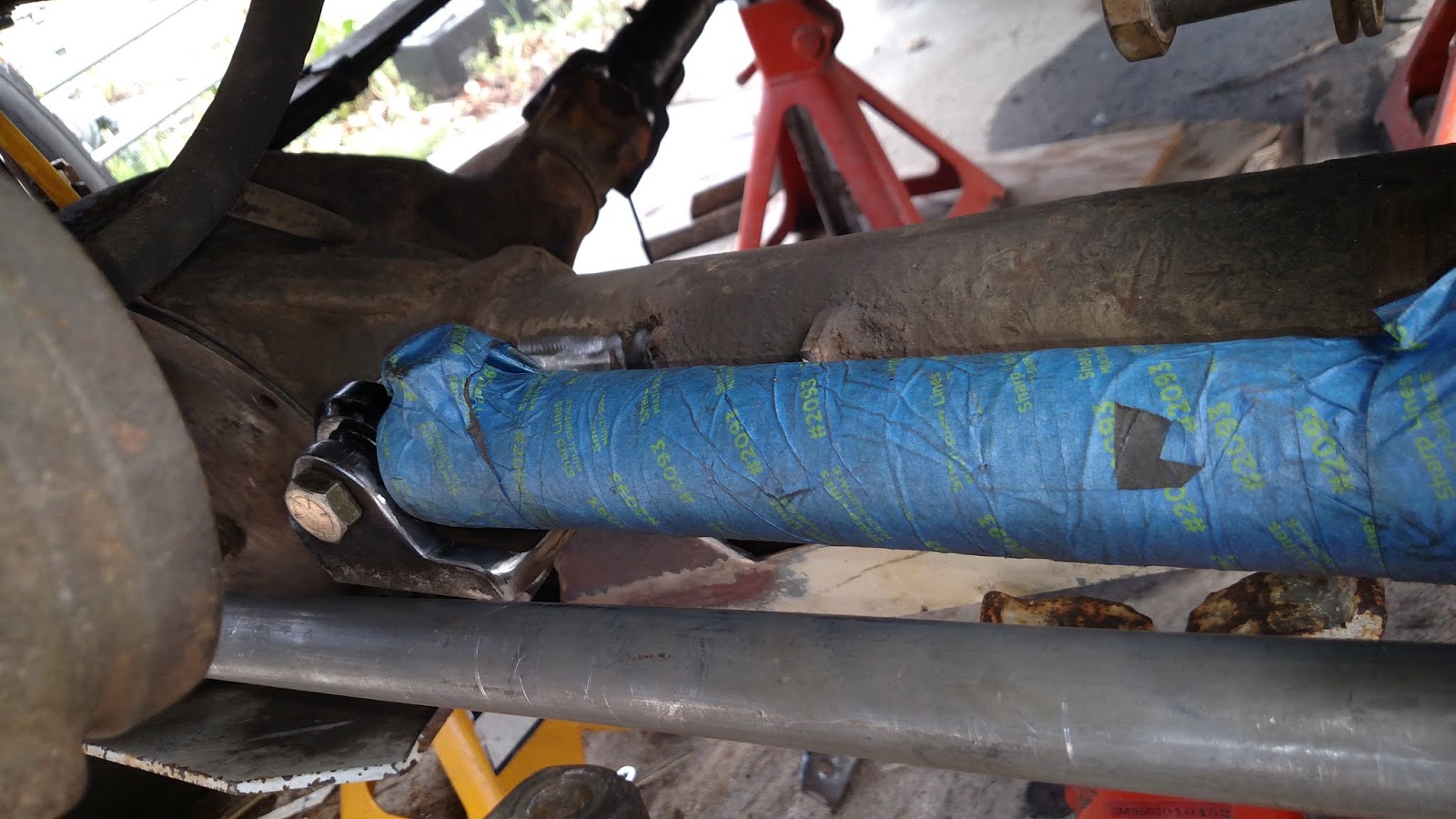
3/27/20: Spent most of Friday installing the axle, tie-rod and drag link under the bus for final installation with new u-bolts torqued to 100 FT/LBS. If you look closely, you can see how small the Pittman arm is. That is why I have decided to add the hydraulic ram.

Need to make some brackets to hold my liquid to liquid heat exchanger. Since I Am adding a hydro assist ram, the power steering fluid will generate more heat, and I need to disipate the heat out so that I don't cook the fluid. Normally, most people would use a conventional radiator type. In my case, I really don't have front air intake and I already had this heat exchanger. With this setup, It should keep the fluid at a constant 180°. Now I need to make a round bracket, but I don't have a roller. Pinched a rubber mallet in the vise and wallah!!


This heat exchanger will have the ability to remove a LOT of BTUs from the power steering fluid.


The rear axle is set in place temporarily to set the spring perches and ladder bar bracket in place. Also got a second set of H1 Hummer 24 bolt wheels with the PVC inserts.

Now it's time to remove the rear axle, finish up the welding and paint.


Good concept that u have done .its nice to see do ur best thing in this
ReplyDelete4x4 Camper Vans
thanks for stopping by. I hope to have more to post soon
ReplyDeleteIt's been almost a year, are you making any progress? Great idea! Now I want a 4x4 VW Bus.
ReplyDeleteSorry for the delay. unfortunately not. So much has been going on lately. I am h oping that within the next couple of months I will be able to hit it pretty hard. Hopefully be driving it by next summer. just keep watching in the next couple of months. Thanks for looking
DeleteThis is an awesome idea, I hope to see it getting finished soon. You could do a similar thing to a VW transporter truck couldn't you?
ReplyDeleteveedubclassics.blogspot.com
Do you mean a Single Cab? Yes your could. To the best of my knowledge, the bottom of the body is the same. The whole reason for the project was to have a 4x4 toy that I could put more people in, go camping in, and still have the same wheelbase as a CJ7. If I were to do a truck, there are some other ways to go that would be MUCH easier, like an old Willy's truck :)
ReplyDeleteThis is an amazing project!! I am very impressed how everything came together. I have wanting to build a 4wd vw bus for years. I did try a single cab design on a full size Chevy frame about 5 years ago. It did not go as smoothly as yours. I really look forward to see more on this build.
ReplyDeleteThank your for your kind words. I haven't had much time to work on it lately (nor the funds). But I do hope to get back to it shortly. Knowing that others appreciate this project gives me fuel to keep going. :)
ReplyDeleteThis blog will help the consumer in the largest purchase they will make for their bus wheels.
ReplyDeleteLight & Medium duty casters & Plastic wheels
keep up the hard work. cant wait to see it finished!
ReplyDeletestay tuned, there will be some more stuff add shortly.
ReplyDeleteFreakin' AWESOME
ReplyDeleteThanks Joe Black
ReplyDeleteCan't wait to see it finished with some action videos.
ReplyDeleteBigC, you are not the only one :)
ReplyDeleteThanks for stopping by, keep watching, there are more pictures coming over the next week.
That's an amazing amount of custom work you've done. Can't wait to see it finished!
ReplyDeleteThis may seem odd, but I have a VW camper bus and I'm dying to find a set of mirrors like the ones on yours. Do you know where to find them or if there is a special term for them? Thanks for any info and great job you're doing
The mirrors were on a Blazer that I parted out. You can try this site:
ReplyDeletehttp://www.truck-lite.com/webapp/wcs/stores/servlet/CategoryDisplay?catalogId=10001&storeId=10001&categoryId=10346
Looks like they have something very similar. Looks like the mirror and bracket are sold separately.
thanks for stopping by. Keep checking in from time to time, there should be more exciting stuff coming up in the near future.
Your getting close! I've been watching this thread for a while now. I love all the extreme fabrication work you have been doing. This beast is definitely one of a kind. Your patience will pay off soon as it looks like your progressing consistently.
ReplyDeleteI have a 69' vw bus and do some off-roading in it. It's the surf mobile. Check it out on Instagram @malibuvwbus is the name. This is why your project interests me.
Cheers,
Sean
Thanks Sean,
ReplyDeletethanks for your comments. You bus looks sweet.
Stay tuned, more updates to follow shortly.
This is so cool! I have been watching your build off and on for about a year and finally finished the whole thing. I cant believe it has taken 5+ years...I am not sure if I would have the patience...but probably. I have access to a Vanagon (for free) that I will help the guy cut out all the Syncro 4x4 stuff and he will give me the rest. If I can I would like to do what you did to the Vanagon...Did you look at any other 4x4 frames that may have been a close fit? I think I would opt for the smallest v8 possible. I like the 60 degree option. I will study your site more. Any videos? Post videos...Thanks for sharing your build! I may have missed it but how did you hook up all the shift levers etc?
ReplyDeleteHello Tyce,
ReplyDeleteYes it has taken every bit of 5 years. Of course there have been long stretches where nothing got done due to either money or time. But make no mistake about it, if you decide to tackle this project you will be making a serious commitment. You will want to quit. 99% of people that start these types of projects do not finish them. Am I trying to discourage you? Absolutely NOT!!! Just be prepared for the reality of it.
As far as using a syncro, there is a guy on TheSamba that is doing it on a Toyota frame & drivetrain.
Other 4x4 frames?
I was originally going to use a truck frame that already had the engine, trans, etc mounted. Just cut the frame and re-weld. In the end, I think that might have been easier. In the end, there are a TON of variables. For example, I custom mounted my engine several inches forward and lower than the stock V8. Why?
*** Keep engine out of passenger area
***Keep the CG as low as possible
***Balance the extra weight that will be in the back
That ended up being a good thing because it allowed my driveline to be 25" long & low enough to clear the front seat frame (by 1.5" with a low profile air filter).
Every decision you make, you will have to weigh out the pros & cons. People will tell you that you "have to do it this way" or "that way". Tell them to go away. Unless they have done it, they don't know. I did it ONE way. Not necessarily the best or worst way, just MY way.
There will be people that will tell you your crazy...it can't be done.... why????...etc. That just fueled me to keep going.
There are a couple of videos on here. I will be working on getting some more high quality videos up shortly.
As far as hooking up shifters, pretty much everything is Morse Cables.
Hey. Tyce here again after 2ish years. i did get the vanagon. I am making it a stretched van as we speak...Im seriously considering making it a 4x4. I have found a rolling 92 suburban chassis with 350 and all the 4x4 stuff. I would really appreciate the opportunity to chat with you live to ask questions about the build...Im on Facebook under Tyce Ferwerda. I moderate a FB group, here is the link. https://www.facebook.com/groups/335575836912767/?ref=br_rs I hope to hear from you asap since the chassis is for sale now and I need to make an educated decision...lol. I have considered using the Astro Van subframe but the width is 78" wide and the Suburban is 72+ iches wide, I measured it last night...Anyway, FB is the easiest way to reach me quickly...I also Moderate a VW DIY autobody group...Thanks for your time and posting of such a cool build...
DeleteYou're getting close at it. Keep it up by making it still upgraded and best keep the features more often.
ReplyDeletegood to see you have it moving ECLECTIC has been at a stand still while I finish compulsory home reno's. I have the front end sitting in situ but still need to work on suspension height. The machining side of the swap is finished. Now all I need is the time to start bolting it together. the next major job is modifying the computer harness to run the engine as a stand alone system I plan on making the entire wiring harness as separate systems lights dash & engine. instead of 1 huge mass of wires. good luck with the finishing of will be watching for your 1st off road video. The way you've built it will give it a lot more ability than mine. ELCELCTIC is more a soft roader
ReplyDeleteThanks guys for following. Hope to have some off road videos by this weekend if all goes well
ReplyDeleteWhere did you get the 90 degree steering box?
ReplyDeleteThe box came off of a piece of agriculture equipment. It will be getting replaced with more conventional U-joints in the near future. Thanks for looking
ReplyDeleteI have a 74 Westy and hope to start my 4x4 build this summer. Your bus is truly amazing and inspired me to attempt this
ReplyDeletebuild!
74 Westy would work great. What is your plan for the build?
ReplyDeleteSo glad I found your blog , thank you for making it . Amazing work & love your enginuity & great attitude. I found it as I'm doing research on building a 74 westy on a Toyota frame (both purchased). Best wishes w everything &
ReplyDeleteGlad that you found the Blog useful and entertaining. I wish you luck on your project.
ReplyDeleteYou did a great job on it !
ReplyDeleteThanks Barron
DeleteRight on! Thats bad ass!
ReplyDeleteThanks for stopping by
DeleteThis comment has been removed by a blog administrator.
ReplyDeleteAmazing! :-D
ReplyDeleteI want one! 😜
Thanks Hugh. You can have one too. Just a little money and about 1000 hours of labor :)
Deletegood to see it running. Way ahead of mine. I have finally sorted out the front wheel drive. I have a Facebook page called modified KOMBI & VW projects if you would like to join.
ReplyDeleteThank you for stopping by. I will take a look :)
ReplyDeleteHola exelente proyectó me gusta les platico soy de la paz baja california mexico ase tiempo estoy en un proyecto como este solo que con una split 62 y un bronco 2 1985 aut 6 cil 2.9 mucho trabajo pero todo bien el proximo año estará rodando
ReplyDeleteEstoy viendo como subir algunas fotos del proyecto
ReplyDeleteGracias por detenerte. Buena suerte en tu proyecto
ReplyDeleteGood work
ReplyDeleteThanks
DeleteA great salute to your great effort.
ReplyDeleteSuch a nice writing. The style you have narrated is simple beautiful and well authored. The quality of writing can be seen from the beginning until the end.
Rocker Panel Repair Derry
Thank you for your kind words. If all goes well, It will drive for the first time with the new front end today or tomorrow!!!
ReplyDeleteWorking on my front Diesel engine bus. 70 bus on top 1982 Isuzu I mark. Thanks for the great work.
ReplyDeleteThank you. Do you have a blog showing work on your project?
ReplyDeleteGreat project! I have a group on Facebook which is just for adding 4WD to VW Transporters like yours.
ReplyDeleteCome and have a look!
https://www.facebook.com/groups/552976292290761/permalink/780395446215510/
Thanks, I will join the group
ReplyDeleteThis comment has been removed by a blog administrator.
ReplyDeleteThis comment has been removed by a blog administrator.
ReplyDelete