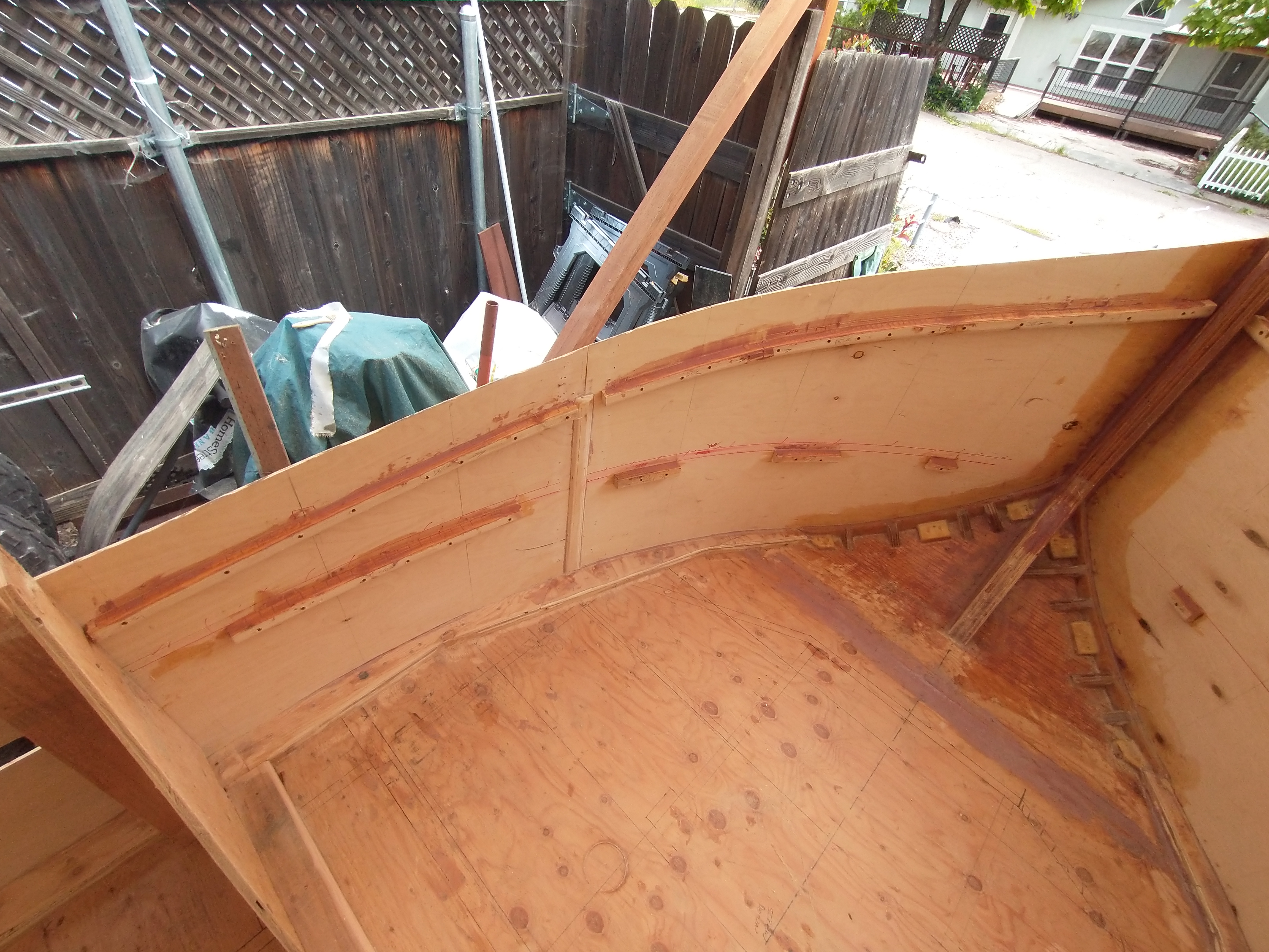
Here you can see that I need to more clearance for the fuel fill hose for the forward gas tank.
Now that it is flat, I will lay down 2 layers of 6 oz fiberglass on the floor and about 3" up the stringers to ties it all back together.
Waiting for more epoxy resin and fiberglass to show up. Then it will be time to get some plywood and start the floor layout.
YEAH...Fiberglass supplies showed up. laid down 2 layers of 6oz on the bottom and wrapped up about 3" on each side.
And now for some bad news...While getting the stringers ready for some fiberglass, I discovered a small hole at the starboard stringer transom junction. My finger poked right in there. I thought that the transom was solid...NOT!!! I thought about cutting out the bad wood and patch in some good wood, but upon further thought, it seemed that it would be easier and definitely stronger to just replace it all.
I think that this ended up being a blessing in disguised. I noticed that the starboard side was never bonded to the plywood. It did make it 30 years like that, but it will be much stronger once the whole transom is bonded correctly.
All wood removed and sanded. There will be a little more clean up later.
1 Layer of 23/32 plywood which is full width. The outer edge shape is pretty close to what the angled hull sides will be. I will trim or extend as necessary once I start building the side walls from the floor to the gunwales.
Center section is 1-1/8" plywood. This will give a total thickness of 1-3/4" which will match the original wood thickness. The width of the original center piece of the transom was only as wide as the stringers. I decided to go a little bit wider to spread the load out. Also, the original center section was not bonded to the main transom plywood, it was only stapled (about 10-12 staples) and then about 2 layers of what looked like 6oz glass. This center section will be epoxy bonded to the main full width piece which will of course be epoxy bonded to the outer fiberglass shell. I will be laying down 2 layers of 1708 full width. This would be good for a V8 powered sterndrive. Since I am only running the Mercruiser 3.0, it will be really strong.
Plywood floor is laid down, not bonded yet. Plotted out the curve dots, and faired to a nice curve.
Cut the floor profile and cut several curve cuts so that I could radius up the tip. The 2x6s are there temporarily to hold the curve. Once the stem gets fiberglass set in place, the temporary supports can be removed.
Applied the peel ply.
Ready to bond floor board #3 (Stations 7,8,8A,8B). Before I do that, I need to build a reinforcement trim piece around the access hole which allows access to the fuel sender, gas/vent line and filler hose to the forward 27 gallon gas tank. This will also be compliant with USCG regulations.
This will get screwed and bonded to the underside of the floor and glassed in place.
3 layers over the access trim ring, and 1 layer over the whole floor bottom surface.
Peel-ply set down over the areas that will be bonded to the boat hull.
Filled in the gap between the fiberglass V-hull and the floor and laid down 3 layers of glass.
Later I will fare in the corners for the final shape, and add several layers of glass again.
OK, here we go, time to start installing the round stern. Sanded off the gel coat down to the raw fiberglass. set into place. There is a 2x2 ripped to match the stock transom to provide a level surface to bond the plywood down to (not shown).
Max turn angle for the Mercruiser Alpha drive is 35° -- Probably the max turn angle for any sterndrive to protect the u-joints.
Angles cut. I did install the sterndrive gimble to verify a good fit and proper turn angle clearances. But unfortunately, I forgot to take a picture :(
It is now screwed and bonded to the stock transom.
The plans call to make a single template that will look like these (or close to it -- modified for this application). After the rear walls are installed, the template is to be removed. This is where I have made another change. I will have 2, and they will be permanently mounted -- now I have knees to help support the new round stern. I did this for a couple of reasons.
1 -- My round stern is separate from the main floor
2 -- This tugboat will go significantly faster than the plans call for and one of the lakes here can get very rough. I wanted some additional structure to take the pounding.
The rear knees are bonded into place.
Installed 4x4 oak support. This will be what the rear tow hook will bolt too. There will be some additional structure to tie this block to the forward structure, but that will be later.
laid in some nice fillets. Once these cure up, I can start laying in the fiberglass to bond everything together.
Getting so close to flip the boat upside down. That might be a bit intense.
Installing the chine logs around the perimeter of the floor. This will provide the anchor point for the hull sides.
The flat area was a piece of cake, didn't take too long. When I got to the bow, this is where the fun began. The tip curves up and in creating a compound curve of sorts. It is really important that I create a vertical surface at the bow to hold the walls vertical when I install them.
I cut 3 blocks on each side. The top one has a 40° bevel cut on the outer edge. The middle blocks has a 20° bevel cut, and the lower is at 0° from vertical.
I then cut 1/2" plywood to match the upward curve of the floor, and had to bend it to match the inward curve to the stem
While I matched all of the curves, I was constantly using a level to make sure that the curve plywood was on a vertical plane.
In the end, I am happy with the end result. I will be adding some additional blocks on the inside to reinforce this mounting surface. This junction can NOT fail!!
Added 4 more gusset blocks to each side
Screwed and bonded the center bulkhead which will located the rear wall of the cabin. This will also give me a consistent square datum from the centerline going forward -- Finally!
Building a bracket for the back of the boat to lift it up. Its time to lift it off of the trailer and flip it to work on the bottom of the hull.
Rear lifting bracket in place.
1/2" bolt to attach the cable to.
Made a front bracket as well to bolt to the stem. I know its a bit rough, but it is temporary after all. Plenty strong.
Engine hoist attached to the stem
Come-a-long attached to the stern
Lifted off of the trailer...just for the record, I was terrified throughout this whole process!!!
Trailer almost out of there.
Starting the rolling process. The balance point was pretty neutral.
Half way there.
Thinking of putting a sign on the bottom of the boat: "if you are reading this -- call 911"
Cut a 2x12 to match the outer curve of the tugboat planform. This will get sanded down to provide a negative chine. This was cut to stick out a bit over 1/4" past the floor. This will provide a "shelf" for the side skins to rest on. Adding this additional chine will also increase the strength on the outer edge.
Starting to fare in the gap from the original fiberglass v-hull and the tugboat planform. Over 100 individual pieces of 1" plywood - each custom cut to fit.
WOW...an ton of work with little to show for it. Finally done cutting and fitting 220 individual plywood blocks. Once epoxy bonded into place, there will be a lot of sanding to smooth out all of the edges. Then fare to the corner edge of the v-hull, then multiple layers of fiberglass to make one continuous shape.
Removed all of the 1" pieces (don't really have a name for them). Mixed some thickened epoxy and filleted the upper and lower corners.
Applied 2 layers of 6oz glass to secure the floor to the side attachment boards and the fiberglass v-hull.
Epoxy bonded the chine rail to the bottom of the floor.
Epoxy bonded 1/2" blocks next to the chine rail to the bottom of the floor. These were necessary so that when the 1" blocks are set into place, and the chine rail gets planed down, it will provide a smooth transition. You will see when we get there :)
Epoxy bonded all of the 1" boards in place
Filled any remaining gaps with thickened epoxy.
As we approach the end of February, I am making some good progress. Bonded all of the blocks in place. Also planed down the chine to be a reverse chine which will put the inside edge close to the blocks which will get a radius fill.
Pretty happy with the way the fillets are transitioning with the strakes.
Quite happy with the way the way this transition came out. Needed to add a Fore-Foot to fill the gap between the stem and the keel.
It's really hard to try and find a picture that shows all of the curves. I am quite happy with how this side has turned out. This is the stem into the fore-foot to the keel.
Let's move to the stern for a bit. This shows the curved rear area of the boat. It will make more sense once the boat is flipped right side up. Normally the floor section would just be 1/2" plywood. However, since I am modifying and existing v-hull, this section is now cantilevered off of the v-hull transom. This structure is similar to a floating shelf: a box bonded to the fiberglass transom. This cavity will not be filled with foam. There really isn't that much space in there anyways. I did completely seal the inside cavity. When completed, it will be waterproof from the inside and out, making this a sealed air pocket.
All epoxy bonded and screwed. Once cured, I will final sand the angles, router the edge and fiberglass to seal all of this up.
WHEW.....All bottom fiberglass is down. 3-4 layers Both sides.
2 layers rear curved stern decks.
There was a valid question asked about how the the floor gets attached to the original fiberglass hull:
There are 2 blocks bonded and bolted to the FB hull. 2 layers of glass connecting the bottom of the floor to the side blocks and the FB hull. Built the new reverse chine onto the bottom of the floor. 3-4 layers of glass from the new reverse chine overlapping onto the FB hull reverse chine. Once the sides get installed, the glass from the walls will overlap the glass on the new reverse chine.
Here is a detailed drawing of the process.
After the epoxy had cured, I found a few air bubbles about the size of the tip of my pinky finger. Probably would have been ok, but didn't like it. Ground those spots down to the wood (tapered bowl shape) and add fresh fiberglass.
First layer of epoxy filler. and sanded down. I think that just one more layer of filler and sanding and I will be ready to roll on the bottom primer.
There was just a small section that still needed to be faired. Small piece of foam bonded to the hull.
Foam sanded down to fit, and laid down the fiberglass. Once my new batch of epoxy and filler shows up, I can finish fairing the bottom.
Bottom of the keel was very chewed up. Not exactly sure how someone managed to get the entire length of the keel so messed up. There was also some gelcoat that was "globbed" on the bottom. Most likely someone's attempt to repair damaged caused by some very rough beaching landing. I decided to sand everything smooth and fill all of the nicks with epoxy peanut butter.

Rolled on the bottom primer. I used Sea Hawk Tuff Stuff primer. It is a 2-part primer that provides an additional water-proofing layer. I have 1/2 gallon left that I will use up to the water-line once the sides are installed. This primer is THICK!!! I will use the Sea Hawk 2053 Thinner for the next run. This primer does seem to appear to provide a nice hard surface. When the bottom paint arrives, I will sand the primer smooth then paint the bottom black. Once I can get the bottom painted, I will then FINALLY be able to flip the bottom hull right side up and start to build up the sides. Can't wait :)
You will notice that I did not apply the primer all the way to the edge. When I apply the fiberglass to the walls, I will wrap the fiberglass around the lower edges onto the existing fiberglass on the bottom.

While I wait for the bottom paint to arrive, I decided that this would be a great time to tackle the trailer. If I am going to put so much time to make the boat look pretty, I want it to sit on a pretty trailer. Everything is getting stripped off. I have all new suspension on the way as well. Currently, this trailer employs an odd slipper spring design. I don't like it. Besides, it appears that when the trailer was originally built, someone welded the rear slider bracket too far aft. With no weight on it, the edge of the spring "hook" is at the horizontal pin. As weight is placed on the trailer springs, the location gets worse. It apparently has worked all these years, but I just don't like it. Besides, these springs are rusty and the trailer sits VERY low which leads to the aft end of the trailer to scrape on the slightest of incline changes.
These rollers on the back of the trailer will be cut off.
Setting new fenders in place. They will be slightly lower that the originals and 1.5" wider on each side.
All sanded down to bare metal and 1 coat of Rustoleum Rusty Metal Primer.
YEAH!!! Time to flip the boat hull right side up!!!!
It is a bit scary suspending the boat from the ends to roll it over, but this system did seem to work quite well. A cable come-a-long on the stern and engine hoist on the bow.
Plans call for 1 90° jig to be placed at the rear cabin wall location to help hold the side wall skins in place. Since I stretched the boat 24", I made 2 - 90° jigs for each side. I can then clamp the skins to these jigs. Worked perfect.
First skin test fitted on starboard side.
Made another quick vertical jig to help hold everything vertical.
Both bow skins set in place.
Quick note here. The plans call for the side skins to be bonded and glassed together-- 12' long. In my case since I added 24", they would be 14' long. And that was my plan. A good friend of mine donated some Matrixx underlayment (Thanks Michael). These are 4'x5'. While test fitting the bow skins, I realized that it would be easier to set each skin panel individually. I screwed 2x4s and plywood planks at the seams to keep them perfectly flat as I went along. Doing this all solo, it worked out quite well. These Matrixx underlayment plywood are fantastic. The glue is waterproof. There are no voids in the laminate. Probably better that marine plywood.
Using straps to hold the plywood vertical.
OK, a little off topic here. I feel that it is important to keep the epoxy resin at a constant temperature. Found a free refrigerator (wasn't cooling very well). Installed a heating element inside along with a thermostat. Keeps the resin right at 72°-73°. The right side is temperature controlled. The left side is just normal storage to keep my supplies organized and clean.
Marking the curve lines onto the side wall skins. Tapping in these baby finishing nails to hold my 6' ruler in place.
Fun fact with these nails. My grandfather loved working with wood as a hobby. Right around 2003, He was no longer doing it and gave me a lot of his wood working tools and supplies. A little bottle of nails was included. For over 20 years, I have moved these with me, but never had any use for such tiny nails. Until NOW!!. They work perfectly to set these curves.
Oh this feels good. Starting to look like a boat now.
Here you can see the chine is still wider that the side skin. Time to remove all of the excess material so that it is flush with the side skin panels.
Nice and flush. Don't know why these pictures are a bit dark. I had the flash on.
Put a layer of epoxy filler into all of the voids.
Installing the aft lower panels. God bless ratchet straps :)
The bottom corner of the original v-hull protrudes slightly on the bottom. This will get a large fillet to blend in the 2 hull shapes.
I am waiting for more epoxy resin to arrive. So back to the boat trailer. Cleaned up the axle.
Wheel hubs were in horrible shape. Axle spindles look great though.
I was going to clean up the original hubs and replace the seals and bearing. Cost for the parts was around $50. I found some brand new galvanized hubs with the more conventional studs (vs using lug bolts -- of which I am not a fan) for $90/pair. So these went into the trash.
Now there is 2 coats of primer on the trailer and axle.
Finished off with 2 coats Rustoleum Gloss White Oil Based Enamel.
Pretty happy with the way it turned out. When I jump back on the trailer, I will install the new wiring and lighting.
Back to boat building. Installed the supports for the front deck and shelf
Ran out of plywood and funds. But I did have some 2x4s. Ripped them down to 2x2s, added some kerf cuts to make the radius, and bonded into place.
Cut and test fitted the deck and shelf pieces. Also cut out the access hatch sides. Currently the dimensions for the hatch sides that protrude into the cabin are larger that what the plans call for. Once I get the cabin walls built up and I get a better idea of how I want the controls to be set up, I will determine what the finished dimensions will be.
Aft rub rail fitted into place along with all of the side hull skins. Those that have built these cute little tugboats know the agony that I went through. All of the varying curves are quite the challenge. First rub rail piece didn't fit very well. OK fine -- not at all!! But now that it is installed, I am quite pleased. Starting to look like a tugboat hull now. Plans called for 4 layers of 1/2" plywood giving a total thickness of 2". I used 2 layers of 1-1/8" (1-1/16" true) underlayment plywood. This gave me a total thickness of 2-1/8". Just a tad thicker. I think that it was easier than getting 4 different layers to meld together.
used 6oz Fiberglass on top side of the deck and shelf pieces. I decided to increase the weight of the fiberglass from 6oz to 10oz. This will add a little bit more rigidity to the overall structure since the tugboat will have the ability to get up on plane with 130HP.
With the stern upper hull skins removed, I was able to fiberglass the inside of the stern lower skins to the original v-hull transom.
Small little hole will get filled and glassed in. The plans call for a temporary jig which sets the location of the rub rail, which it turn sets the shape for the stern hull skins. Since I am blending 2 hull shapes together, I needed to make some design changes. The floor which sets the shape of the tugboat planform is 2 individual pieces. 1 forward of the transom, and 1 aft of the transom. Instead of having 1 temporary jig in the center, I made 2 of them, rotated about 40 degrees and spread apart to clear the sterndrive. These parts are an integral part to the structure of the boat now. Tying the stern section to the transom.
June 2024
Busy, busy, busy.....
Forward gunwale fit. There is a small gap between the gunwale and the forward stem. No big deal. I can fit in a small piece to fill the gap. Once epoxied in place and glassed, it will perfect.
Laid down 6 oz fiberglass both sides of the forward hatch.
Time to bond in the lower shelves
Fitting the aft gunwale
Bonding in the forward deck.
I was trying to figure out how to hold both of the forward hatch walls vertical, parallel, in the same plane, and square all at the same time. I cut a piece of 1-1/8" plywood PERFECTLY square and screwed it at the top of the walls. The screwed 2x4s to the bottom of each side wall to set the height at 14.5" off of the floor. This allowed me to move the hatch walls as an assembly. Worked very well. It is now bonded into place with more epoxy. Weather has gotten very warm. Shop area has reached 110° a couple of times, but need to keep chugging along.
Fitting the aft gunwale supports
Fillet and glass the aft rub rails to the upper side skins.
The side of the boat makes a great place to write notes and reminders.
Fit and bonded the forward rub rails. This was another one of those "not-so-fun" jobs. Multiple pieces that have to curve in and up, and all be held together 'with epoxy going everywhere!!!
Once the epoxy has fully cured, I can remove the screws and sand to the final shape.
So one final note on the rub rails and gunwale.....HOLY CRAP!!! For those that have built one of these, I am sure that you will agree. All of the curves are an absolute pain in the rear!!! For those that are thinking of building one, just be fore-warned, you will need to take some extra time and don't get too frustrated. Double check every measurement. If something moves even the smallest amount, walk around and double check all of the fitments. Make everything larger than you think it will need to be and then bring the parts down to their final size slowly. I still have some sanding to do to get the rub rail and gunwale down to the final shape. In the end, it is very rewarding to see it all come together.
A bit warm in the workshop lately.
Here are some close up shots of the gunwale and rub rails. Edges are routered. Filling and sanding all of the gaps to provide a nice smooth surface.
Time for a break. Threw a neighborhood block party BBQ for the 4th of July. Had a great time with some friends.
Wow, I guess that it has been a while since I have updated this. It is now September 1st. I had to take a week off of the boat project for the Central Coast Renaissance Festival. Then another 3 weeks to work on the Triumph Spitfire: Replace the entire wiring harness, all new gauges, half of the switches, fuel pump, replace both door handles, and learned how to install a windshield -- yippee. Then got back to the boat.
I laid down some fiberglass on to the aft stern upper skins. Then I made a recessed box for the rear tow hook. I could have just bonded a block to the inside of the skin and screwed a standard tow hook, but I really wanted something a little special here. Recessing it ended up giving it a really clean look. The boxed section is 1/2" plywood bonded to the skin and the 4x4 oak block that the will anchor the hook with through bolts, not just some screws.
This 4x4 oak block is bolted and bonded the the 3/4" transom support which is bonded and glassed to the transom and stern skins.
Lower ledge is sloped down about 5° to prevent any water from pooling inside the recess.
Now for some bling-bling: new massive bow-eye and the rear tow hook.
Setting the rear tow hook in place, I felt that it was recessed in too far.
Bonded and glassed in a 3" thick wood block to bring the tow hook out a bit more. I really am liking the look of this.
Here you can see the difference in size from a standard bow-eye, and the one that is going on the tug boat. The stem on the boat is 6" deep (versus the plans which called for 3.5" deep). This bow-eye is 8" long (5.5" past the mounting flange). So I will have to cut out a relief in the inside to provide room for the backing plate and nuts. No pictures of that yet.
Worked on fairing a nice fillet from the aft lower skin to the rear corners of the original v-hull bottom. Found a great use for those old incandescent light bulbs that we no longer use. Just the right size for a good fillet.
Fillet and radiused the front stem to the gunwale -- sorry for the blurry pic.
Sand - Fill - Sand - Fill - Sand --Rinse and Repeat. OMG -- my arms were killing me. There is now way to convey the amount of sanding that is required to get to the point of laying down the fiberglass. I could have just laid down the glass and fill any necessary voids later. However, I felt the the better that I could make the initial surface now, would mean a lot less work later.
Yeah!!! it's fiberglass time. Plans called for 1 layer of 6oz fiberglass. Due to the higher speeds and the lakes around here can get a bit rough, I increase the fiberglass by 40% -- 10oz.
I discovered a neat little trick. I use tacks to hold the glass in place while I applied the resin.
I trimmed of the lower half of the glass since my goal here was to cover from the top of the gunwale to the bottom of the rub rail. Later I will glass in the lower half to the top of the rub rail which will give me 2 layers of 10oz fiberglass around the rub rail.
Top half of the boat is now completely encased in 10oz fiberglass.
Time to lift the boat off of the stands, set it on the ground, and lean it over so that I can do the finish work on the lower half of the hull. Rear tow hook and bow-eye worked great as lifting points.
Lower chine routered with 3/4" bit. Still lots of sanding to do and fill any little voids to create a smooth bonding surface for the fiberglass.
Sanding, filling, sanding, filling -- Rinse and Repeat!!!
Finally time to lay down some more 10oz fiberglass. 1 layer over the side skins. overlapping over the rub rail for a total of 2 layers. 3 layers along the lower chine and the bow to stem joint.
There will be some trimming of glass hanging on the bottom, but I will wait on that for now.
Pretty happy with the way this little overhang turned out. This little section was a point of great contemplation. This little corner tip is part of the original v-hull of the Four Winns donor boat. I wanted to cut this tip off to allow for a continuous smooth round shape which defines the shape of a tugboat. As I weighed the pros & cons, my largest concern was how the boat would handle up on plane without those corner tips. Although looks are hyper-critical to this build for me, I also want a stable - comfortable ride. I felt that leaving these corner tips in place will add that stability. These will also not be seen once the boat is in the water. Once painted with the flat black bottom paint, most people probably won't even notice them. Well except for those of you who have taken the time to read this far down in this blog :)
October 25th 2024
Time to shift gears here. My original plan was to finish the outside lower section of the hull (sand, primer, & paint) and then put the boat back onto the trailer. This would have been a great milestone. We are now at the end of October and rain will be on its way in the near future - albeit the weather has been beautiful this last month. The boat project is under cover; however, it is not completely shielded when a bad storm comes in. I don't want the floor to get wet and absorb any water. Spent some time filleting inside corners and router the outer edges. I also worked on filling any void in the plywood and joint/seams. Next will be to sand all this filler down smooth and get some fiberglass laid down on the floor. I will not worry about the walls at this time, just want to seal the floor.
1 layer 10 oz glass on the cabin floor.
Running out of hardener, so shifted to the port rear since that is where water can get blown in from the storm that is on its way. went from "running out" of hardener to OUT :(
Had to stop laying down fiberglass at this point.
Time to get the new bunks on the trailer.
November 2024
This trailer has come a long way from what it looked like 1 year ago!!
1 layer of filler to blend in the fiberglass overlap seams starboard side.
Found a bubble too big for my liking. This one section has been a pain in my ass! I have fixed it twice, and the glass just wont conform. I was hoping that I could get the glass to bond to the wood, and then I could fill in as necessary. NOPE!! Ground out the fiberglass.
Filled the low spot. I will sand perfectly flush and put 3 layers 10 oz glass over it.
Starboard side: after sanding down the seam filler, spread filler on entire surface to fill in the fiberglass weave. My arms are going to hurt after sanding this.
Everything was going great, and then all of a sudden my compressor head decided to completely lock up -- SOLID! There was oil in it. I have had this compressor for over 10 years and have running it pretty hard, so I cant complain too much. Bought a Vevor compressor head and installed. It doesn't make the air as fast as the Quincy, but is is a lot quieter. If I find that I need more air, I can change the pulleys to increase the speed. I am pretty sure that I am under-spinning the compressor right now. But I really like that it is not so loud.
Sanded down starboard side lower side wall. One more layer on necessary spots. Hopefully this will be the final filler layer before primer. I am just focusing on everything below the rub rail for right now so that I can get it up on the trailer.
Not done with the bottom yet. But I really wanted to get it back onto the trailer.
Inching in the trailer. Having a single axle trailer defiantly made it easier to maneuver.
It is hard to tell in this picture, but I ran into a HUGE problem here. The bunks were set onto the trailer centered on the bunk brackets. That's how it is supposed to be -- Right?
Well, I guess not. The strakes at the front of the hull would be resting directly on the bunk...hmmm. How the heck did it sit before? Never dawned on me to take pictures of below, before I took the boat off of the trailer.
And of course one other problem reared its ugly head. The distance between the top of the fender and the bottom of the boat. Now, I knew ahead of time that the boat is going to overhang over the fenders. That is why I lowered the fenders a couple of inches as well as moved them each out 1.5". Figuring out exactly how far was an educated "guess". I took as many measurements as I could, but without a solid reference point, it was quite challenging. I was close, but the gap ended up being only .75". That was a bit closer that I would prefer. And since I had to re-do the location of the bunks to fit the strakes on the bottom of the hull, time to get creative.

Removed the bunks (with the boat overhanging the trailer fender). Cut redwood blocks to attach to the bottom of the bunks. That did 2 things for me: allowed me to raise the boat up a bit to better clear the fenders, and set them into place in an effort to miss the strakes. Seems simple enough. It took me all day to get it right. I am almost wondering if the bunks should have been 2x4s instead of 2x6s. In either case, I did finally get it set so that it all fits. I may have to do some minor adjustments in the future. Who knows.
About 1.5" of clearance now. Not huge, but I am ok with it. Everything is a compromise. I really don't want the boat any higher.
Looks bigger now that it is sitting up on the trailer.
Pulled the boat out so that I could get the Mercruiser 3.0 up on the engine stand to determine what the condition of the engine is.
Engine at it's resting place for the time being. Time to check it out.
YUCK!!! This was not what I was hoping for. Looks like at some point, one of the past previous owners allowed it to sit out exposed. Water came in through the carburetor into the cylinders.
Time to completely tear everything apart. So to be clear here. I am a pretty decent mechanic. I have been fixing all of my own vehicles for all of my life - couldn't afford to have someone else do it :)
That being said, I have never rebuilt an engine before. I have helped others, assemble one from time to time, but never a full build on my own. Lots of learning gonna be happening here.
Stripped down
The worst cylinder was #4. Used a 3-stone hone. Managed to take .011" out. For those that don't know, that is a HUGE amount to remove with just a hone. In reality, most people would say to take it to a machine shop to have it done. I simply just do not have the money. My time is free. This one cylinder took me 3 hours holding my drill. My arm and drill were not happy with me. I still have a bit more fine work to do to get the proper cross hatch pattern in it.

Well...here comes some bad news. I was successful at removing the indents in the cylinder walls with the 3-stone hone. However, after measuring the bore of the cylinders, and then the piston skirts, I realized that I had a .016" piston to cylinder gap. Spec calls for .0025-.0035. So now I have no choice but to take it to a machine shop to have the block bored .020" over and buy new pistons and rings. I was hoping to just buy new rings. I should have measured the piston clearance on cylinder #4 before working on #3 & #4. Lessons learned -- c'est la vie.
And the cabin build begins.
Cabin walls are cut and set in place. All windows are rough cut out. The plans call for making custom window frames with tempered glass. I have decided to go with new RV windows. I wanted to make the windows as large as possible.
This angle is hard to see, I can't really get a good side picture when the boat is in the shop area. The plans called for the side window to be in the neighborhood of 18" wide (don't have the plans in front of me at the moment - about 1/2 of the wall). I wanted better visibility, So these are going to be 24"H X 30"W. The 3 front windows are the same at 18"W X 24" tall. Quarter windows are set inline with the side panel windows, with the front center window raised up several inches.


Side bench boxes cut and set into place. Rear center deck support cut and set into place. The seat boxes will be bonded a fiber glassed permanently to the boat. This will add even more rigidity to the hull. Plans call for the sides to be bare. For a mere 16' boat, this is a massive amount of standing space - about 4'x4'!! Center deck support (between side bench boxes) is designed to be removable for easier engine maintenance and installing the motor. There will be removable floor covers in the existing holes in the floor. These access holes are necessary to have access to the 2 fuel tanks under the floor for maintenance and per Coast Guard Regulations. What else can I get done this weekend?
New Years Day 2025 -- Got a lot of work done today.
Built the back deck. It is huge. At 5'10", I can lay across the front, and not touch the other side. I still need to install some internal supports, but it completes the inside layout.

Lots of standing room. 48"x50"
Fitted the roof today as well. Once again, I am deviating from the plans. Plans call for the side of the roof to be cut flush with the side walls. Then install the eyebrow to finish the look. I chose to extend the sides out 4".
I also changed the overhand at the back of the roof. Plans called for 4"-5". I made it 12".
Cabin door cut and fitted. Decided to also build an integrated door jamb as well to hold the door more secure when closed and be more weather tight. It also stiffened up the wall significantly.
Decided to make some changes to the windows on the rear wall. After sitting inside make motor noises and looking at the view around, I realized the the visibility while looking back was horrible. Huge windows were needed in the rear. I am quite please with the changed look.
Now for some tedious work. The RV windows require 1.5" wall thickness. The walls are 1/2" thick. I am cutting 2 layers of 3" plywood strips to make window frames around each window. This also serves to stiffen the walls quite a bit.
If it's not 120° in the summer, it's now 34°. Temperature be dammed...must get back to work. Although a shop would be nice :)
Layed up fiberglass on the inside on the dash panel and Underside of side dash panels.
Dash assembly is bonded is now bonded into place along with the forward triangle flat inserts.
There is something oddly satisfying using a razor knife to cut green fiberglass.
All of the window trim pieces are now bonded in. That is 8 trim pieces for 8 windows = 64 custom cut trim pieces. I will admit that these took much longer that I planned.
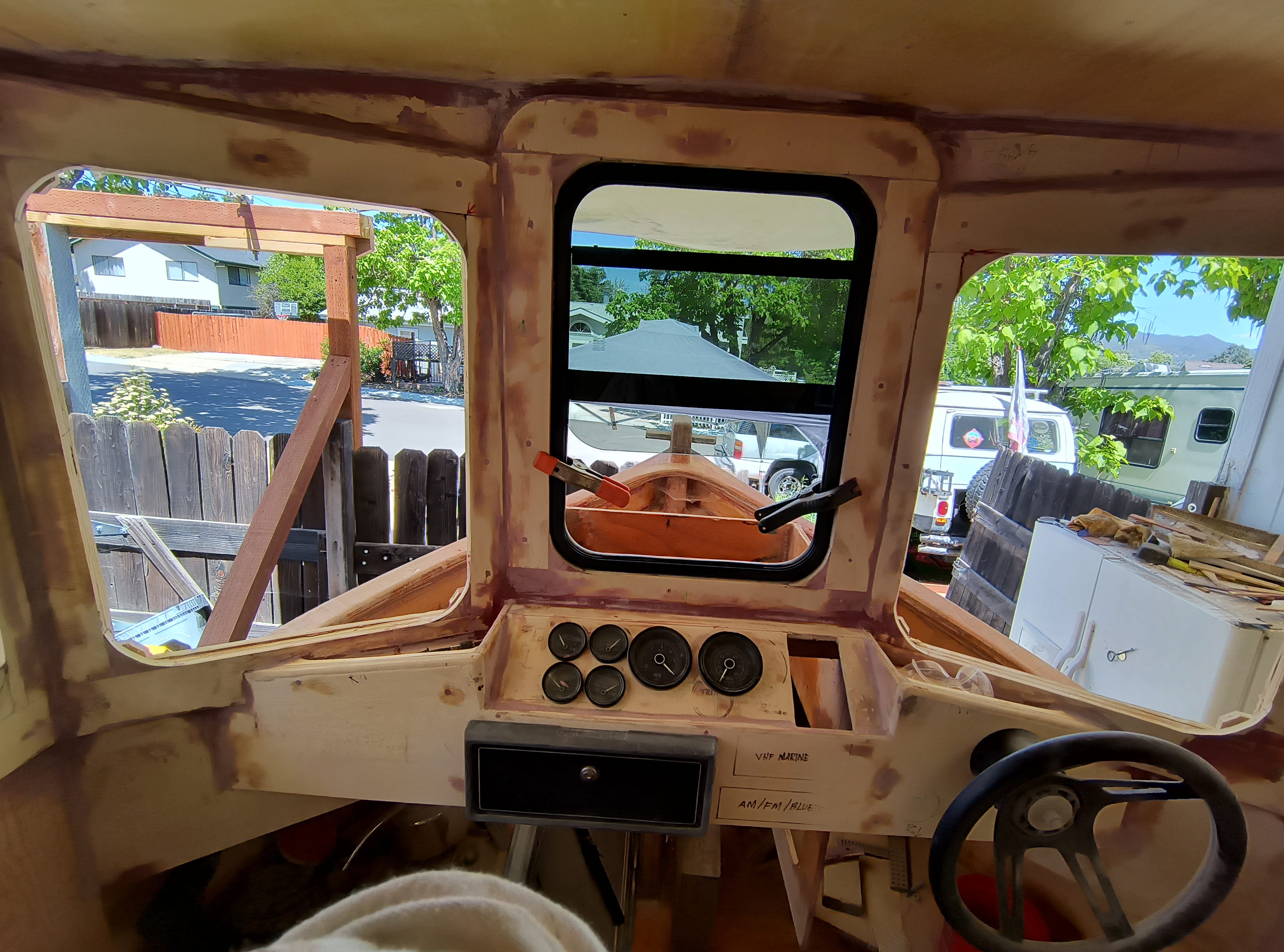
Most of the helm is cut. These gauges are temporary - just for a reference. I will be getting new white faced gauges.. I do love the twin handle throttle shifter though.
Removed all of the plywood for the bench seats so that I can fiberglass them while they lay flat. Much easier and makes for a better layup.
For the front bench seat panels, I placed American flags under the fiberglass. Everywhere you see wood will be painted. The flags will get clear coated.
While the bench seats were out, I was able to pull the cabin back wall and then bond it back into place.
The back flag was a prototype to see if the process would work for the flags. That piece of plywood is 1-1/8" thick. It may seem overkill, but servs several purposes:
1 - A ledge to bond the plywood seat base.
2 - The forward box area will be a sealed subwoofer box. I didn't want the bass pulses flexing the 1/4" plywood walls. The thicker plywood will do that instead.
3 - I needed something to support multiple items such as amplifiers, battery disconnects, wire/cable supports, etc. This will allow me to screw anything I want without worrying about penetrating the boat hull sides.
Back cabin wall. In the plans, this would simply be the 1/2" plywood for these "wings". Don't know what else to call these. I added a 2x2 to make it look more finished. It will also deflect any water that happens to come down the deck surface in the event that I stuff the bow in a big wave so that water will not soak someone sitting in the bench seat.
Bonded 1x2s inside the bench seat structure. This will allow more surface area for bonding and well an a larger radius to allow the fiberglass to lay down nicely.
Temporarily installed the stern drive to see how it will look. It is not quite in all the way. Final location will sit about 5" further forward. I will also be making a removable stern curved section which will complete the lower radius of the stern.
Fill and sand. Fill and sand.
Looking like a tugboat :)
8" speaker holes cut in the rear wall. Lift off hinges are temporarily fitted. Also fitted the RV style door latch tot he door.
So this one is just funny. Oil pressure is at 80 PSI, RPM is over 6000, And I am overheating at 240°. But wait....there is no motor in the boat...hehehe. Good thing I am getting new gauges.
Found some seats. My original plan were to have some larger, much more luxurious seats. However, after placing some temporary seat with the dimensions that I wanted, I discovered that there would only be 10" between the seats in the middle. 10" is just too small to comfortable walk between the seats. These seats are much narrower. Not as comfortable as the original plan, but I believe that they will work OK. These are height adjustable, which as a side benefit, allows some vertical movement - like shock absorbers, in rougher water. I will work on some floor mounts to secure them with quick disconnect so that they can be removed easily to allow for an air mattress to be put in there if we choose to camp.
Time to finalize the roof. Here it is flipped upside down. 2 layers of 6oz glass, each layer offset from the center line 1.5". The roof is being held in the curved shape.
The screws that you see are there to hold the 1/4" piece of plywood on the other side to hold the 2 halves together. Once the 6oz glass strips cure, the screws can be removed, and then the whole surface can be glassed. The resin here was the 3:1 medium cure. This resin does leave an amine blush when curing. Since I have raw wood on both sides, I did not want to have to wash it off with water, possibly allowing water to soak into the wood. So I use some peel-ply. This will leave the center glass strips ready for the fiberglass overlay.
It was a bit cooler outside than I would prefer, so I place a tarp over it to make sure that the temperature for the roof panel stayed high enough - long enough. Worked FANTASTIC!!! Temperature under the tarp here as 119°.
Removed the peel-ply. Laid down 1 layer of 10oz fiberglass over the whole surface. I am changing to a different hardener now. As the temperature is starting to warm up, I am switching to the 2:1 slow hardener. This does a couple of things for me: 1-Much long working time, so I can take all the time that I need to get all of the bubbles out and make it look Quite nice. 2-The slow hardener does not produce an amine blush on the surface of the fiberglass; therefore, I will not need to wash it off after it cures.
I am just using a 4" foam roller to lay down and spread the resin. Very happy with this process. Very even resin distribution and no bubbles. No need to even use a bubble buster finned roller.
Having such success last time I used the tarp trick, I decided to do it again. The slow resin must have a minimum temperature of 73° for at least 3 hours -- bare minimum! Digital thermometer showed the inside temperature was 120°. Once the sun went down, I placed an old quilt over the top to hold the heat in as long as possible. It will also keep the temperature of the tarp itself from dropping down to the dew point - down want any condensation inside overnight.
Once cured, I flipped the roof over and put down 1 layer of 6oz glass down the center seam and 1 layer 10oz over the entire top surface. But apparently, did not take any pictures of that. But that's OK, it looks pretty much the same . I used the tarp trick as well. Cured great.
Getting the door ready for fiberglass. 1"x2" stringers down the side and 2 layers of 1/2" plywood so that I can get the appropriate thickness for the RV style door latch. All edges fileted. Need to so some more sanding.


Roof is now bonded onto the top of the cabin. Very satisfying. This is the few of the front. Another change that I made, deviating from the plans, is the elimination of the roof cross-over supports (left to right). These supports are to help add some rigidity to the roof as well and hold the curve of the roof when bonding the roof on top of the cabin. Inside roof height was very important during the initial thought process of this build. I wanted a full 72" of head room inside. To accomplish this goal, 2 things needed to be done: 1 raise the dimension of the cabin slightly. 2- remove the lateral supports. If you remember looking at the picture of the roof being fiberglassed, you will have noticed that the roof is held in a curved position while applying the fiberglass. This means that when the roof panel was place on top of the cabin, the roof is already holding a curved shape. Plus, I used 10oz fiberlass instead of 6oz. The roof is quite rigid.

Rear few. The gap in the middle at the roof-line is intentional. This gap will allow any wiring to pass through. I will make a nice removable cover later.
Weights holding down the roof while the epoxy cures. I also clamped an additional piece of 1/4" plywood along the bottom to help keep the curve smooth while everything is curing. I really the look of the additional thickness. I think that I will go ahead and permanently bond it into place. This will also add some additional rigidity since it does hang back much further than the original plans. I will also provide some additional support for the custom bimini top that I have designed. But you will have to stay tuned for that gem.
Another change that I made for the roof is the overhang on the side. Plans call for the top roof panel stop at the side cabin wall panels. I have an overhang of 4" on both sides.
Time to fiberglass the inside surface of the door. There are a lot of curves her. I was very concerned that the 10oz fiberglass would not lay in the corners very well. I witch up to 4oz glass here. I don't need any additional structure, the doors is quite rigid. And since I have designed this door to be easily removed with lift hinges, weight is important.
The 4oz laid down quite nicely. Once again, I covered it with the tarp.
Outside of door is covered with 10oz fiberglass. Not for strength so much, as for abrasion resistance.
Ordered some windows. Quick trial fit in the door. Love the way the look.
Looks like I made a small mistake. When I cut the holes for the windows, I used too small of a hole saw. This left a small gap in the corners. Had to clue in some spacers on each outside corner. On I had to do the same for the inside corners as well. But at least I knew that I was going to have to do this since the internal frames are at 90°. This took a grueling amount of time. Once the glue cures, I will be able to sand it down to the appropriate radius.
Since I extended the roof out to a total of 11", I wanted some additional strength. I laminated an addition 1/4" piece of plywood on top of the after roof section, this makes this section 1/2", making it much mor rigid.
I have been been trying to figure out how I wanted to do my hawse pipe. The plans call for making a mold, then mixing a batch of epoxy resin with portland cement. Once removed, fill & sand smooth. This would have been a very time consuming process. There had to be a better way. An old friend moved back into town and has been playing around with a 3D printer. And I thought--- Ah-Ha!. I send him a 2D CAD drawing. By the end of the night, he had printed up a prototype. Thanks Rob! I even like the color - no paint required. Although, I think I might go with red instead. I will buy him a roll. Thant will give him plenty of extra for any other project that he wants to do in the future.
Windows fitted Fitted to door and rear walls.
Inside view. The boxes are speaker boxes to 2 8" 2-ways on each side. The will also double as pathways to run electrical wires and tubes for the air horn. The top gap above the door/roof line will have a cover installed to hide the wires.
Front center window fitted. As you can see, these vertical has a large divider in the middle of the window. This is just fine for the center window and the rear windows. However; for the quarter windows, t his would be horrible. While driving the boat, that center divider would be right in the line of sight -- yuck!!!
Bonded in place and set in the sun to cure.
Rubber trim installed and trial fit on the cabin. I will leave these on for awhile, until I am ready to prime and paint. This is the safest place for me to store them.


.jpg)